Magnetic Resonance Imaging Compatibility of the Polymer-based Cochlear Implant
Article information
Abstract
Objectives
In this study, we compared the magnetic resonance (MR) image artifacts caused by a conventional metal-based cochlear implant and a newly developed liquid crystal polymer (LCP)-based device.
Methods
The metal-based cochlear implant system (Nurobiosys Co.) was attached to side of the head of a subject and the LCP-based device was attached to opposite side. In both devices, alignment magnets were removed for safety. Magnetic resonance imaging (MRI) was performed on a widely used 3.0 T and an ultra-high 7.0 T MRI machine. 3.0 and 7.0 T MR images were acquired using T1- and T2*-weighted gradient echo sequences, respectively.
Results
In the 3.0 T images, the metal-based device on the left side generated the significant amount of artifacts. The MR images in the proximity of the metal package were obscured by the artifacts in both axial and sagittal views. On the other hand, the MR images near the LCP-based device were relatively free from the artifacts and clearly showed the brain structures. 7.0 T MR images showed the more severe distortion in the both sides but the metal-based cochlear implant system caused a much larger obscure area than the LCP-based system.
Conclusion
The novel LCP-based cochlear implant provides a good MRI compatibility beyond present-day cochlear implants. Thus, MR images can be obtained from the subjects even with the implanted LCP-based neural prosthetic systems providing useful diagnostic information. Furthermore, it will be also useful for functional MRI studies of the auditory perception mechanism after cochlear implantations as well as for positron emission tomography-MRI hybrid imaging.
INTRODUCTION
Cochlear implant is the most successful sensory neural prosthesis to restore hearing among sensorineural hearing loss patients. Cochlear implants have been attached in more than 120,000 deaf people and they have an excellent perception performance rate of 80-90% average speech in a quiet environment (1). However, there remain many problems, such as patient variation, music/tone perception, speech recognition in a noisy environment, sound localization, and so forth. In clinical aspects, another major problem of the present-day cochlear implants is the incompatibility with magnetic resonance imaging (MRI) due to the interference between the magnetic field and the metallic package of the implantable unit.
Conventional cochlear implants consist of an external speech processor and an implantable unit. The implantable unit is composed of a platinum coil, an alignment magnet, electronic circuits, titanium packages, and an electrode array. Among them, the most harmful factor in the magnetic resonance (MR) environment is the implant magnet for the coil alignment because MRI machines use superconducting magnets for the hydrogen alignments of the body. Even though a compression dressing can keep the magnet from moving in the MRI machine, an exposure to the strong magnetic field can cause the demagnetization or the polarity change of the magnet (2-4). Furthermore, the magnet can severely deteriorate the MR images (3, 5). Fortunately, in the commercial cochlear implant systems, the magnet can be easily removed temporarily during MR imaging even though the local anesthesia and the small incision are necessary.
Medical grade titanium packages are widely used in cochlear implants and other neuroprosthetic devices to protect electronic circuits from body fluids and vice versa. Titanium is not a ferromagnetic but a paramagnetic material. Therefore, it does not cause a missile effect under MR environment but generates image artifacts by the surface scattering of radio frequency (RF) pulses in the MRI machine. The MR image artifact hinders the diagnosis of brain-related diseases in cochlear implant recipients. As an alternative means, computed tomography (CT) can be used especially for the detection of intracranial hemorrhage. However, MRI is better than CT in detecting acute ischaemic stroke (6). MR compatibility is important not only for the diagnosis of brain diseases but also for the neuroscience studies that offers a top-down approach in cochlear implants as well as other neuroprosthetic devices. To date, the MR image artifact has blocked the use of MRI cognitive neuroscience tool or a top-down approach, which is the investigation of neural pathways from the primary cortex to the sensory nerves. Traditional methods to improving the performance of cochlear implant systems have employed bottom-up approaches that focus on electrical stimulation to the cochlear nerve. With this approach, it has been difficult to explain why some patients can listen to music with single channel cochlear implants while other patients have poor speech perceptions even with multi-channel devices. To solve these problems related to the higher-level action of perception, we have to understand the delicate structures, functions, connectivity, and plasticity of the brain. Powerful imaging techniques, such as ultra-high tesla MRI, functional MRI (fMRI), and positron emission tomography (PET)-MRI fusion imaging technique are essential for this top-down approach.
It is known that commercial cochlear implants are MR safe under specific conditions. Nucleus 24 and Nucleus 5 (Cochlear Co., Sydney, Australia) are safe for MRI scans up to 3.0 T and 1.5 T, respectively, with the removal of the alignment magnet. HiRes 90K (Advanced Bionics Co., Valencia, CA, USA) and SONATA-TI100 (Med-El Co., Innsbruck, Austria) are MRI safe at a maximum of 1.5 T. However, MR safety does not mean there is no MR artifact in the images. All the commercial cochlear implants are hermetically packaged with titanium cases, so it does generate a certain degree of MR image artifacts. One solution to achieving MR artifact-free implants is to use a polymer encapsulation instead of metal packages. Polymers are inherently RF transparent; thus, it does not generate image artifacts in MRI. Despite this advantage, polymers have not been used for chronic implants mostly because of water absorption. Most biocompatible polymers, for example, polyimide and parylene-C, show a relatively high water absorption rate and they degrade in aqueous environments over time. Lee et al. (7) have shown that polyimide and parylene-C encapsulations failed within 66 and 117 days, respectively, in accelerated soak tests in phosphate-buffered saline.
Recently, high-performance liquid crystal polymer (LCP) films have been shown as the most promising material for the encapsulant of chronic implants (8). LCP films are thin, flexible, mechanically stable, and biocompatible materials that have an extremely low moisture absorption and permeability. Lee et al. (7) have shown that LCP encapsulants were intact after more than 300 days in an accelerated soak test. Furthermore, they have shown that the LCP film with metal patterns implanted in a rabbit's eye was well preserved without degradation and caused no infection over a 3-months postoperative period (9). LCP films have several advantages as an implant material in addition to the low moisture absorption and excellent biocompatibility. LCPs are thermoplastic polymer, and as such, the implant electronics can be encapsulated easily with LCPs by a thermal-press bonding process. In addition, LCP films can be used as a substrate for electrode arrays through semiconductor thin-film processes. Thus, we can easily fabricate the high-density cochlear electrode array and achieve a monolithically integrated system. Finally, LCPs have an extremely low dielectric constant and dissipation factor, and these characteristics make them ideal for high frequency applications, such as RF telemetry as well as MRI (10). It suggests that coils for power and data transmission can be easily integrated into the LCP films. With these unique properties of LCP films, we can build novel, thin, miniaturized, and MRI compatible neuroprosthetic devices, as well as cochlear implants.
In this paper, we report on the MR image artifact difference between metal- and LCP-based cochlear implants. Components and fabrication methods of both devices are also briefly described.
MATERIALS AND METHODS
Metal-based cochlear implant sample
We adopted the Nurobiosys Nuvoc-A01 implant as a metal-based cochlear implant sample (11). Electronics for power receiving, data decoding, and current stimulation are encased in medical grade titanium packages. Output from a current stimulator chip is delivered to each site of the cochlear electrode array by platinum feedthroughs. Each feedthrough is insulated by a ceramic plate. The joint area between a ceramic plate and a metal package is hermetically sealed by brazing. A platinum coil for power and data transmission is located outside the metal package. A neodymium magnet encased by titanium packages is located at the center of the coil. Joint areas of the metal packages are fused by laser welding. Metal packages, coil, and a magnet are molded by a medical grade silicone elastomer. The magnet is placed in the silicone elastomer pocket, so it can easily be removed and put in. The electrode array is made of Pt:Ir (90:10) wires. Sixteen flame formed ball contacts are encapsulated by a silicone elastomer. Fig. 1A shows an overall apparatus of the Nuvoc-A01 implant. The bottom panel shows an enlarged view of the sixteen-channel cochlear electrode array.
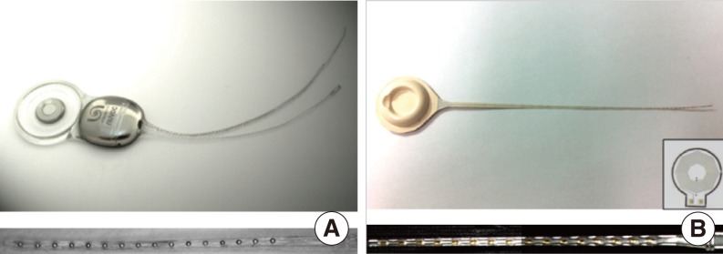
Nurobiosys' metal-based cochlear implant system (A) and first prototype version of the liquid crystal polymer (LCP)-based cochlear implant system (B). Bottom figure shows extended view of the each 16 channels electrode array. Inset of the (B) is the 1 cm-diameter LCP-based planar cooper coil for power and data transmission (7).
LCP-based cochlear implant sample
The overall fabrication procedure for the LCP-based cochlear implant is similar to that described by Lee et al. (7). Electronics and coils are fabricated from LCP films with copper cladding. High-resolution laser cutting is used to cut the board outline. Electric components are soldered to fabricated LCP circuit boards. Metal patterns for the sixteen-channel cochlear electrode array are deposited on the LCP film using semiconductor thin-film processes, including photolithography, metal deposition, and lift-off. A laser-cut LCP cover for a passivation layer is aligned to the patterned LCP film and laminated by heated press. The laminated film is cut into a cochlear electrode shape using a laser-cutting machine. The LCP-based circuit board and electrode array are connected to each other using a biograde silver epoxy. LCP package lids are thermoformed by heated aluminum molds. The thermoformed LCP package lid is aligned with the LCP-based circuit board and fused along the outer lines using the heating press machine. Both package and electrode array can be molded with silicone elastomer to provide a magnet pocket and to cover the sharp edge of the film. Fig. 1B shows the first prototype of the developed LCP-based cochlear implant system. The bottom panel shows an enlarged view of the LCP-based cochlear electrode array molded with a silicone elastomer. The inset shows a 1 cm-diameter LCP-based planar coil for data and power transmission that is integrated into the LCP package (12).
Experiment protocol to measure MR image artifacts
Metal- and LCP-based devices are attached with a paper tape to the left and right side of the subject's head, respectively, to compare image artifacts simultaneously. Fig. 2 shows the experimental setup that compares MR image artifacts using both devices. For both devices, the alignment magnet was removed for safety. Two MRI machines were used: a 3.0 T (Magnum, Medinus Co., Yongin, Korea) and an ultra-high 7.0 T research prototype MRI machine (Magnetom, Siemens Co., Erlangen, Germany). Currently, the 7.0 T MRI machine is not available for clinical use. Generally, signal to noise ratio of the MR images is nearly proportional to magnetic-field strength. Thus, we can observe the delicate structure of the brain using 7.0 T MRI even with multiple brainstem nuclei. We included the 7.0 T MRI machine in this study because it will become clinically available in the near future and will eventually substitute the 3.0 T MRI machine. A T1-weighted gradient echo technique (TR, 400 ms; TE, 9 ms) was used to acquire 3.0 T MR images. 7.0 T MR images were acquired using a T2*-weighted gradient echo technique (TR, 576 ms; TE, 17.8 ms). Axial and sagittal plane views of the head were obtained to compare image artifacts created by the two units.

Experimental setup to compare magnetic resonance image artifacts caused by metal- and liquid crystal polymer (LCP)-based cochlear implants.
RESULTS
Fig. 3 shows T1-weighted 3.0 T MR images of the head with the metal-based implant attached to the left side of the head and the LCP-based implanted on the opposite side. Fig. 3A and 3B are the axial and sagittal images of the head, respectively. In Fig. 3A, brain imaging of the left side is obscured by artifacts. The diameter of the artifact caused by the metal-based cochlear implant was approximately 69 mm. Contrary to the metal implant, very mild artifacts were generated by the LCP-based device on the right side. A similar tendency was observed in the sagittal image of the head (Fig. 3B). There exist extremely small artifacts on the right side, while severe image distortion was generated on the left side by platinum coil and titanium packages. Therefore, if we use an fMRI to see the neuronal activity from the auditory brain cortex of the metal-based cochlear implant recipients, it will be impossible to monitor the ipsilateral temporal lobe that was applied to the primary auditory cortex. It should also be noted that the distorted area of the MRI images can be smaller compared to the images of the CI recipients, since the metal- and LCP-based cochlear implants were attached to the outside of the skin, and not fully implanted inside the skin.

T1-weighted 3.0 T magnetic resonance images of the head: axial (A) and sagittal (B) plane views when the metal- and liquid crystal polymer-based cochlear implants are attached to the left and right side of the head, respectively.
Fig. 4A and B are the T2*-weighted 7.0 T MR images of the axial and sagittal plane of the head, respectively. Since the spatial resolution is higher than the 3.0 T images, sulcus, gyrus, white matter, and gray matter are clearly distinguished. An identical device configuration was used to compare the artifact between the two implants. Similar to the 3.0 T images, severe artifacts created by a metal-based implant were observed on the left side of the metal packaged cochlear implant, while mild artifacts were observed on the right side. In 7.0 T images, a magnitude of the artifacts caused by LCP-based implant was slightly larger than 3.0 T images. It is likely that the LCP-based planar coil (inset of the Fig. 1B) is more interactive with the RF coil of the 7.0 T MRI machine than the 3.0 T MRI.
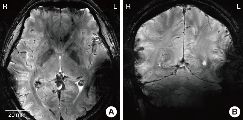
T2*-weighted ultra-high 7.0 T magnetic resonance images of the head: axial (A) and sagittal (B) plane views when the metal- and liquid crystal polymer-based cochlear implants are attached to the left and right side of the head, respectively.
DISCUSSION
In this study, we compared the MR image artifacts caused by metal- and LCP-based cochlear implant systems. The magnitude of MR imaging artifact of the LCP-based one was much smaller than the metal implant in both 3.0 T and 7.0 T MR scans. It provides us with many possibilities to investigate the cognitive neuroscience or the top-down approach in neural pathway research; in particular, brain plasticity after deafness or cochlear implantation that is of interest among several researchers. One of the major reasons requiring such studies are that the variations of the cochlear implant performance depend on different patients. It has been reported that patients using the exact same cochlear implant system have a broad distribution of outcomes. For instance, some patients can hear monosyllabic words in noisy environments. On the other hand, there are patients who show poor sentence recognition even in a quiet situation. If we can monitor the auditory connectivity and the related brain plasticity while the functioning cochlear implant system remains inside the subject, it will be possible to develop a more powerful and effective cochlear implant system.
Recently, various innovative brain-imaging techniques have been developed, enabling us to understand the delicate structure and the functionality of the brain. Cho et al. (13) suggested a fusion PET-MRI system with a high-resolution research tomograph-PET and an ultra-high field 7.0 T MRI. Using this novel hybrid imaging technique, we can observe the human brain with higher temporal and spatial resolutions. Thus, MR compatibility with implantable neuroprosthetic devices will become increasingly more important along with the development of innovative high-Tesla MRI systems.
The MR compatibility is an unavoidable issue in all implantable neuroprosthetic devices, such as deep brain stimulation (DBS) systems and pacemakers. In DBS systems, electrical pulses are delivered through a macro electrode that is implanted into a subthalamic nucleus or internal globus pallidus (GPi). A conventional implantable pulse generator (IPG) of the DBS system is implanted in the chest area, and a long lead cable is used to connect the electrode array and the IPG. During MR scans, the long lead cable acts as a resonant antenna. Therefore, RF-induced heating occurs in the electrode sites (14-16). This may lead to brain damage or a patient's death. To overcome this serious problem, some companies are currently developing a head mountable DBS system, which has no or very short lead wires. However, there remains an MR image artifact problem caused by metal packages of the implantable pulse generator (IPG). The use of LCP-based packages can minimize this artifact as shown in our study. It can also achieve an extremely smaller and thinner packaging for the IPG than conventional ones. Furthermore, a high-density LCP-based DBS microelectrode array can be monolithically assembled using automated semiconductor thin-film processes.
ACKNOWLEDGMENTS
This work was supported in part by Interuniversity Semiconductor Research Center, Seoul National University (SNU); in part by the Ministry of Knowledge Economy of Korea under Grant 10033657-2011; in part by a grant from the Korea Health 21 R&D Project A050251, Ministry of Health and Welfare, Korea; in part by the Ministry of Education, Science and Technology under the Smart IT Convergence System Research Center (SIRC-2011-0031866) and the Public Welfare & Safety Research Program through the National Research Foundation of Korea 2011-0020987; in part by BK21 Project, Department of Electrical Engineering, SNU in 2011; in part by Pioneer Project (2012-0001038) of the Ministry of Education, Science and Technology of Korea.
Notes
No potential conflict of interest relevant to this article was reported.